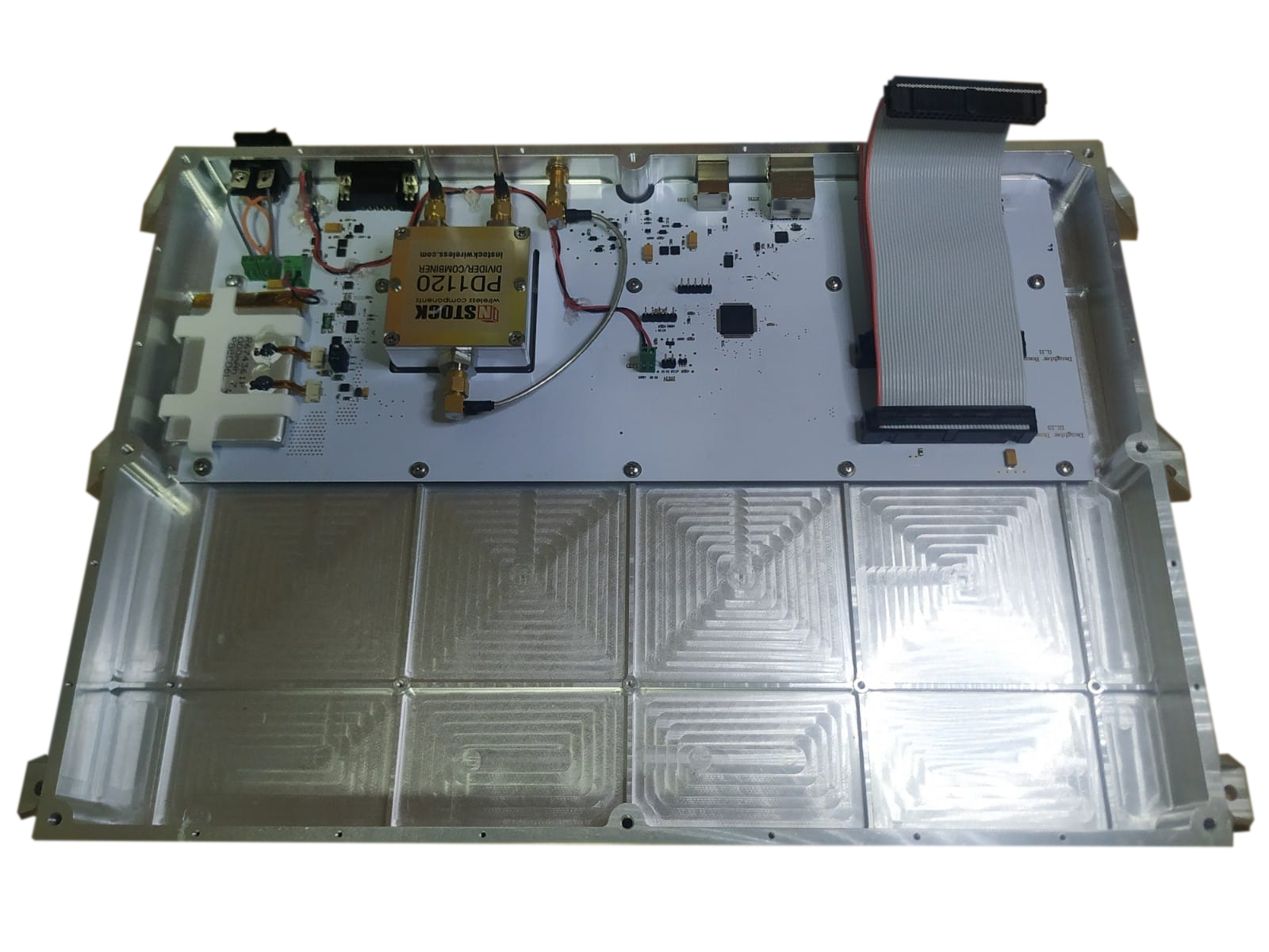
An RF radar system with power supply control and distribution unit has been designed to calibrate and optimize all RF paths.
Figure 1 - RF Radar Control Unit Box
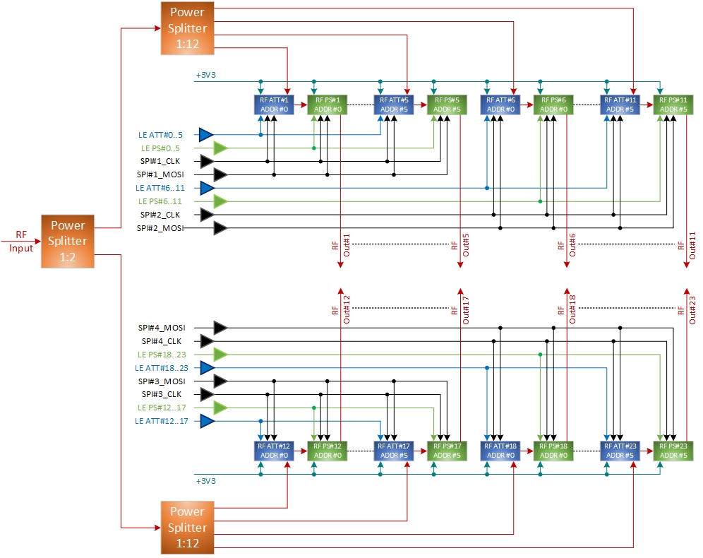
A single Rf input is first splitted by two and then fed to two 1:12 power splitters to get 24 RF paths. Each RF path can accurately controlled by changing attenuation and phase.
Figure 2 - RF Radar Control Unit Block Diagram
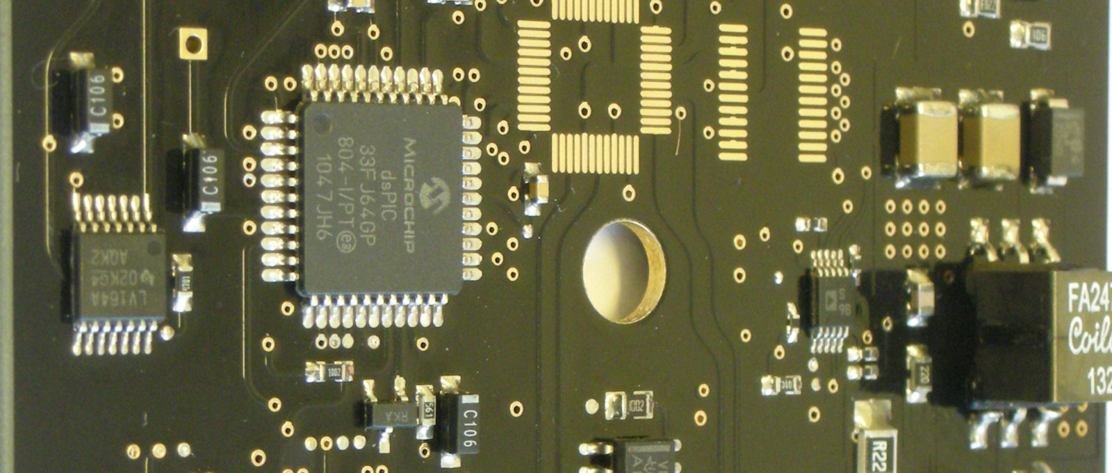
The system is composed by one digital and power distribution mainboard and two signal condition and RF control slave boards. All RF paths are digitally controlled by the mainboard equipped with a microprocessor. All digital channels are buffered and filtered to improve noise immunity.
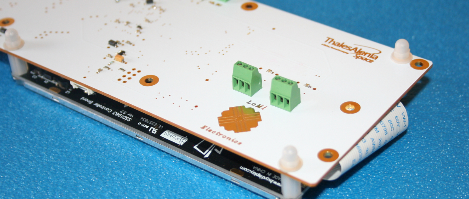
The RF unit can be powered by an external power supply or by USB 2.0 port.
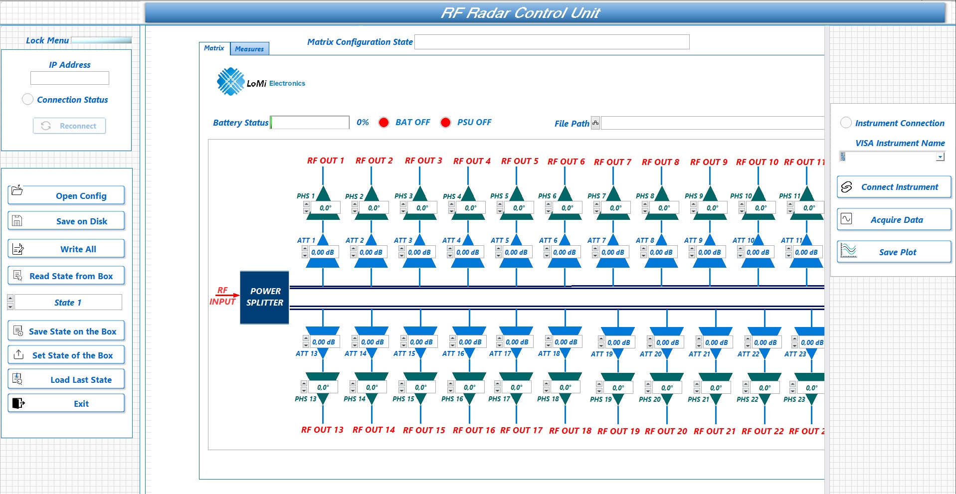
A battery backup system allow to overcome voltage drops during radar rotation due to sliding contacts. The system is remotely controlled through an ethernet physical link and a LabVIEW interface.
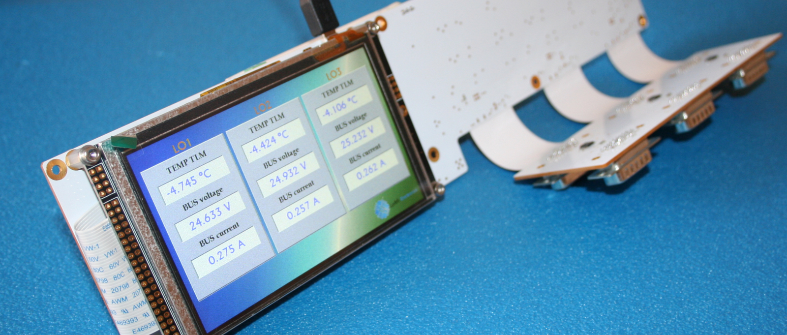
Figure 3 - RF Radar Control Unit LabVIEW Interface
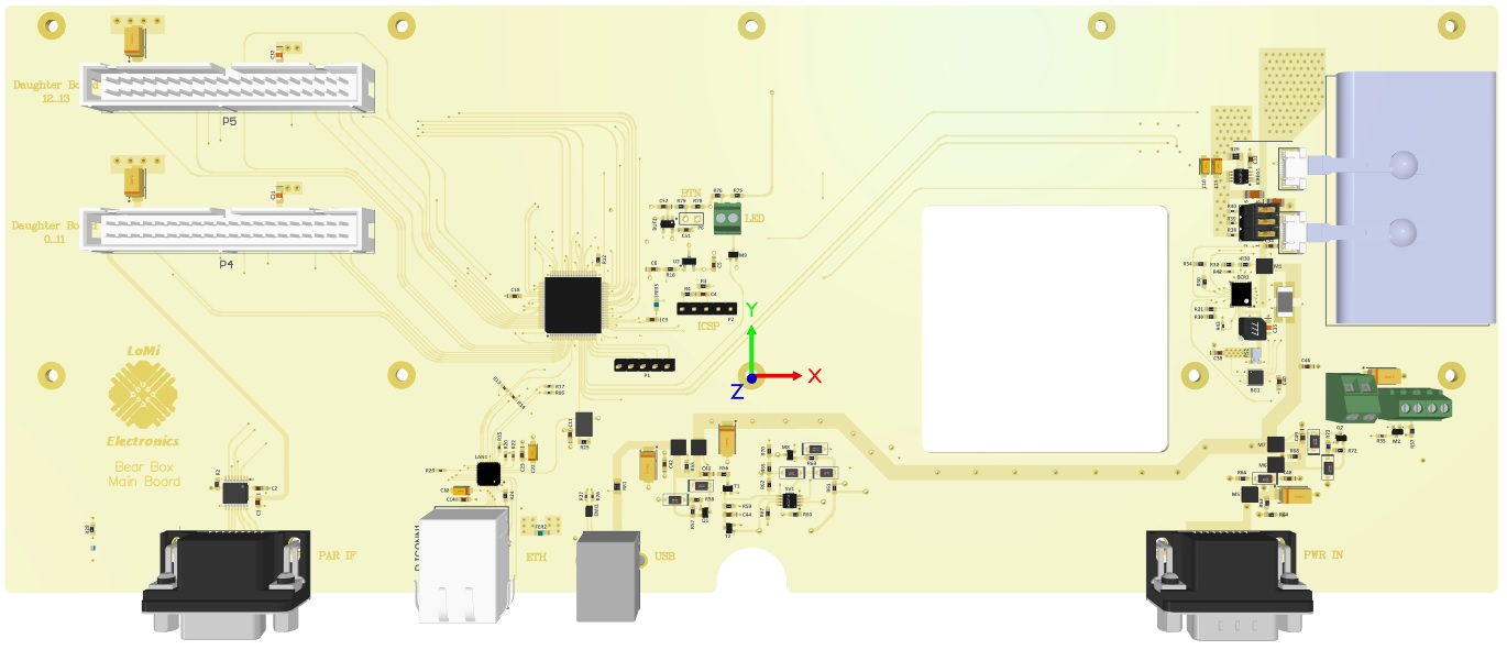
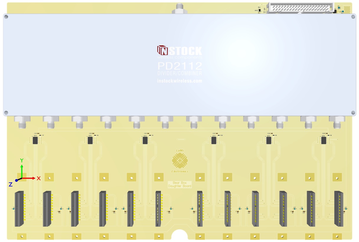
The main and daughter boards were designed on a multilayer rigid PCB while for the RF modules a RO4350B substrate was used. Next figures show a 3D view of the main and daighter boards.