Automatic Test System for a Radio Frequency Unit

A complete automatic test system was developped starting from hardware level to firmware and software.
The Hardware projected relates on three main units:
- A Radio Frequency Unit Communication board with a multi link RS-422 and ECSS BSD serial protocol
- A bidirectional Radio Frequency Switch 1 Pole 4 Through (1P4T) with control board and relative firmware and GUI
- Three 1 Pole double through (3 x 1P2T) Radio Frequency switch.
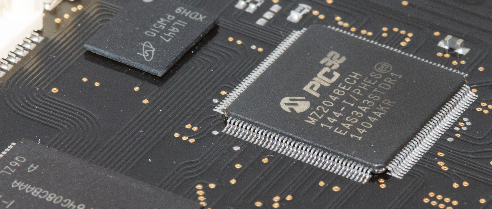
Radio Frequency Control Unit
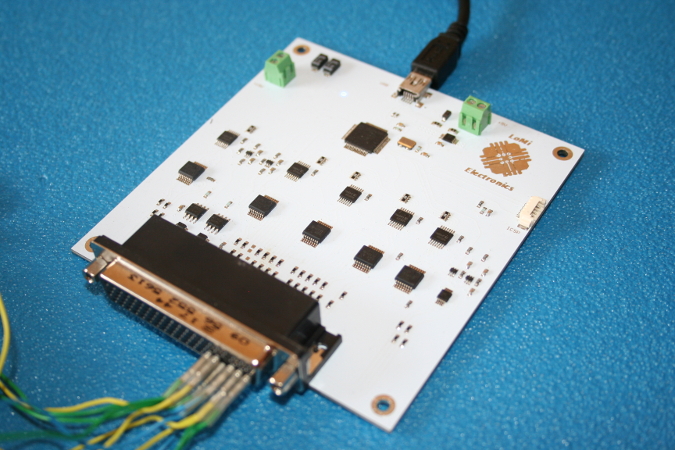
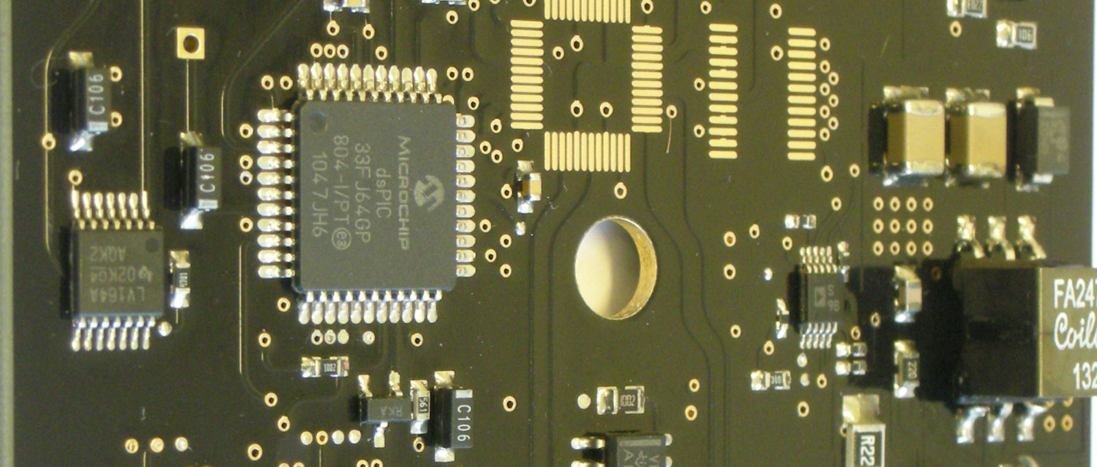
Based on 32-bit Micro Controller Unit (MCU), a multi-link RS-422 control board was realized to monitor and drive radar unit signals. An ESA BSD standard link was implemented to retrieve the RFU telemetries. Thanks to a USB link, a LabVIEW graphic interface was designed to show and control the system.
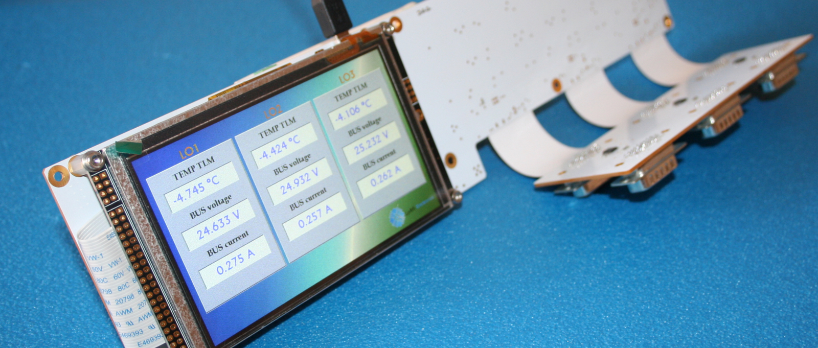
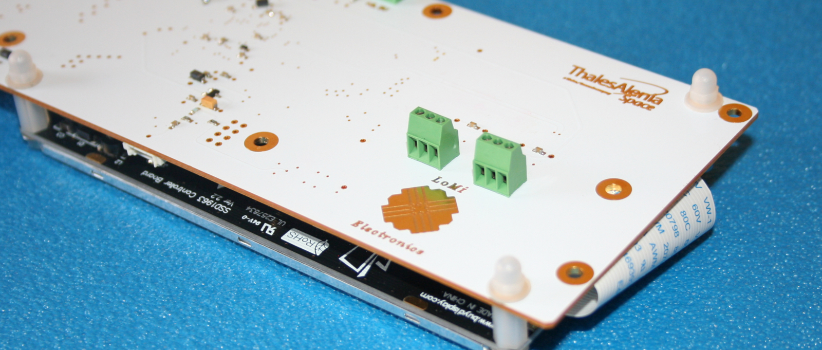
High voltage power supply monitoring and distribution with CAN BUS and TFT display
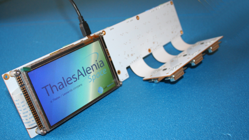
A power supply control and distribution unit were designed to supply and split a 100V rail on three loads. Current and voltage telemetries, besides thermocouples and status flag are acquired through a 12-bit ADC and digital I/O lines. All telemetries are shown on an 800x480 TFT touch display. An USB link is available to show the same data on a graphical user interface designed in LabVIEW. A dual CAN BUS link is available with programmable addresses. A multi channel load control unit was designed. The board was designed on a multilayer rigid-flex PCB.
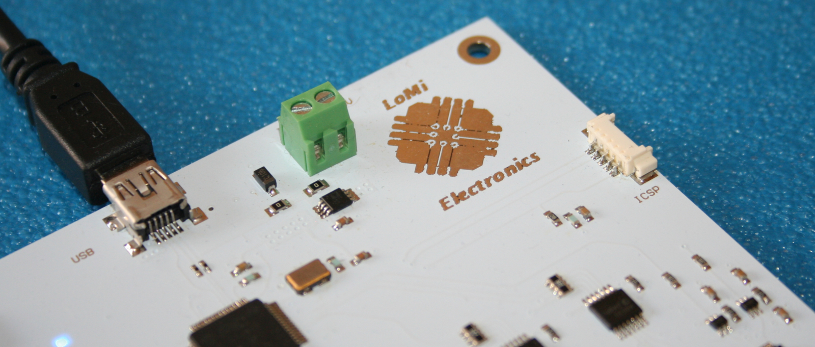
NRP2 power meter remote monitoring interface
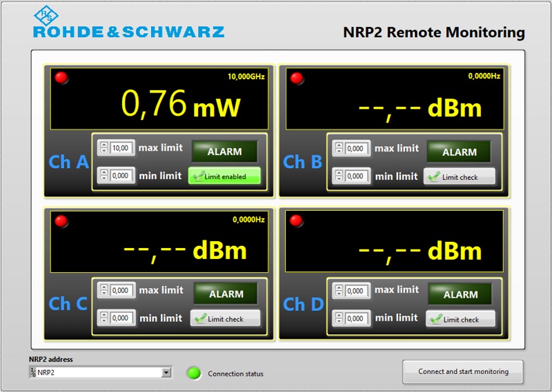
A remote monitoring interface was developed to allow data capture and storage from NRP2 four channel power meter instrument. The interface can be customized to control the instrument too with a friendly Graphical User Interface. Visible and audible alarms are available if the measured value falls in the settled range. A list of different log and control interfaces are available or a new one can be developed for a lot of instruments.
RF radar control unit
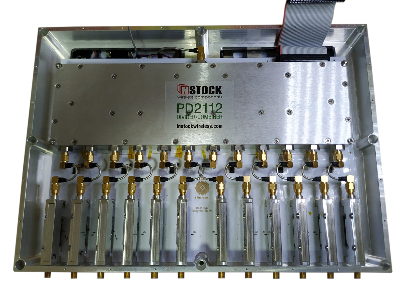
A novel monitoring system for an RF radar control unit was developed. By Starting from a single RF input, the RF power signal is splitted by two and fed thorugh two 1:12 power splitters. Each 1:12 power splitter output fed an RF module equipped with an attenuator and a phase shifter in order to set attenuation and phase shift accurately.
A remote monitoring interface was developed to allow data capture and storage from the control unit. The sysem can be powered through external power supply or USB 2.0 interface. A battery backup system was adopted to overcome voltage drops during radar rotation due to sliding contacts.