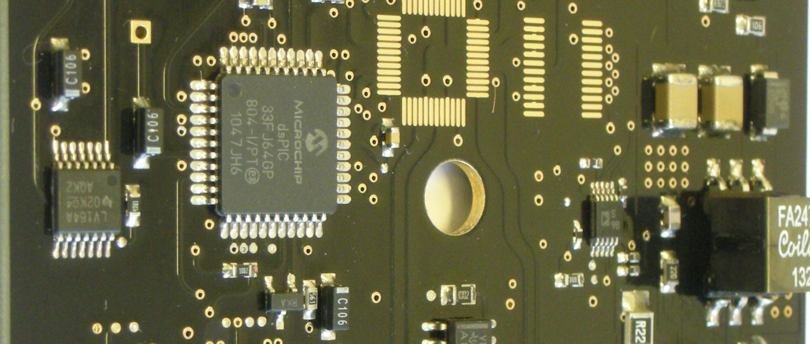
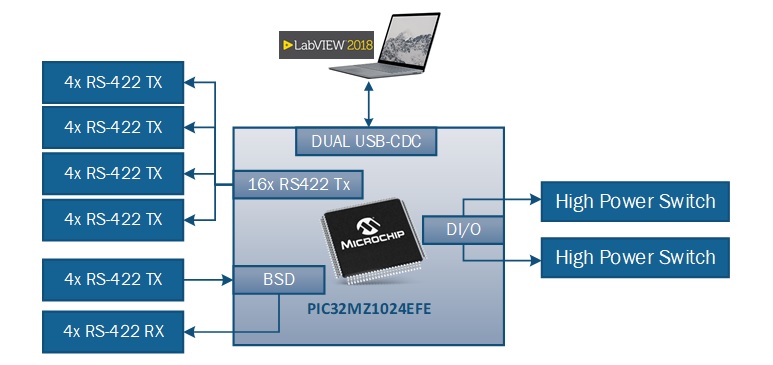
A Radiofrequency control Unit has been developed using a 32-bit Micro controller PIC32MZ Microchip. The board is controlled remotely through a dual channel USB, one used as debug and the other for Labview communication. Commands sent automatically or by the user, permits to set the RS422 communication for the Main Unit.
Figure 2 - RFU Board Block Diagram
16 RS422 TX Channels have been implemented through the Microcontroller to transmit the configuration for the Main Unit.
Using a line driver (AM26LS31) and a level translator (ADG3304), MCU signals have been adapted to RS-422 standard.
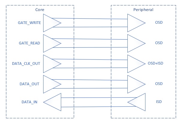
In addition, a 16 bit Bidirectional Serial digital interface (BSD) has been provided as a standard ESA protocol. It offers the possibility of writing a data value out to a peripheral element and then reading the same value back in order to verify that the write operation was performed correctly
Figure 3 - BSD Communication
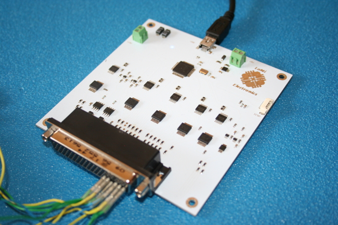
Two High power switch (VN750PS) are added to switch on/off the Main Unit remotely through a Labview interface.
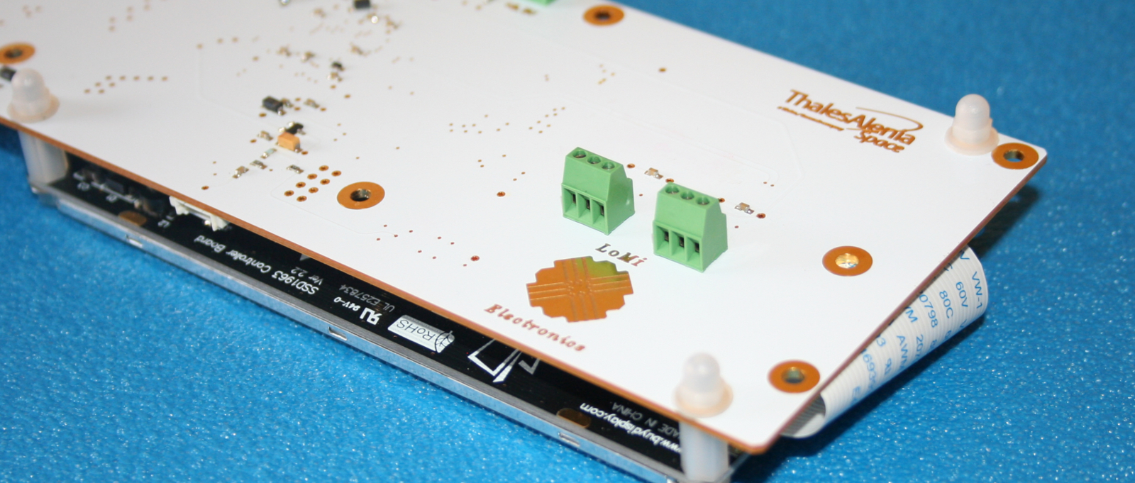
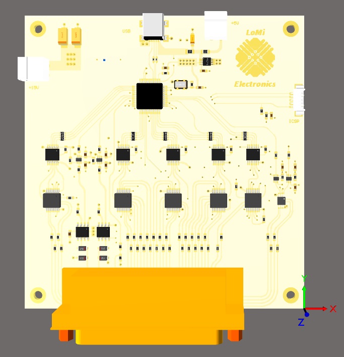
A Four Layer PCB has been developed to be included in the mechanical rack.
Figure 4 - 3D PCB Board
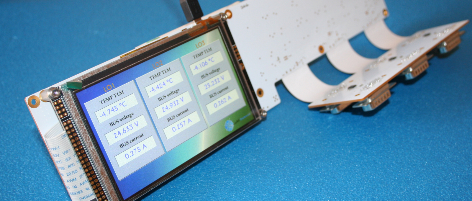
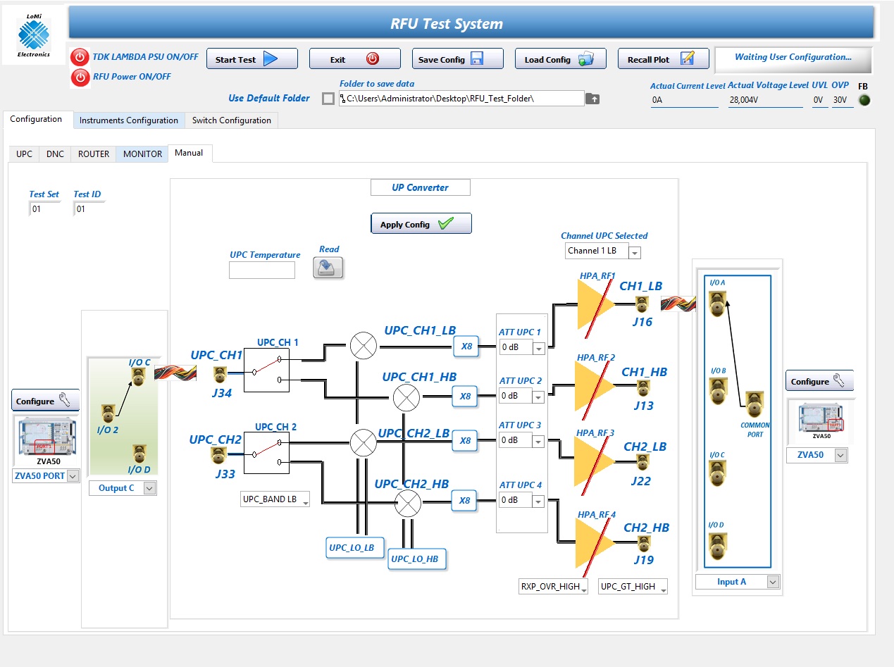
Labview Interface permits to control the RFU board, switch on the Main Unit attached to the High Power Switches, load a preset test configuration and set all parameters to control the main unit. All the buttons and the configurations items control specific part of the main unit sending a specific RS422 command.
Main Unit Telemetries can be read back in order to know the register status. Furthermore, two RF Switches are connected to program automatically the different channels of the Main Unit and Configure the Instruments (Vector Network Analyzer, Spectrum Analyzer and Signal Generator)